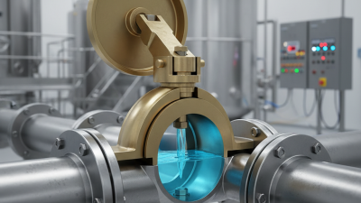
7 Tips for Choosing the Right Butterfly Check Valve
Selecting the right butterfly check valve is a small decision with serious operational consequences. A failed valve can cause reverse flow, water hammer, pump damage, or unplanned shutdowns. In a chilled-water line, that failure may appear as vibration near a pump discharge. In a wastewater system, it may begin with a leaking seat and rising maintenance costs.
Industry data shows why valve selection deserves closer attention. MarketsandMarkets’ Industrial Valves Market report estimates that the market will grow from approximately USD 78.7 billion in 2023 to USD 101.9 billion by 2028. This expansion reflects wider investment in water treatment, energy, chemical processing, and industrial infrastructure. However, market growth does not guarantee correct specification. A butterfly check valve must match the medium, pressure class, temperature, flow direction, pipe size, and installation position.
Standards offer a reliable starting point. Engineers commonly consult API 594 for check valves, ASME B16.34 for pressure-temperature requirements, and ISO 5208 for leakage testing. These references improve confidence, but they do not replace field judgment. A valve that performs well in clean water may struggle with abrasive slurry or frequent cycling. That difference matters.
The following seven tips focus on practical selection. They examine body materials, disc design, cracking pressure, pressure loss, sealing performance, certification, and maintenance access. Small details matter. A lighter disc may reduce water hammer, yet it may not suit every flow condition. The honest answer is rarely the cheapest valve. It is the valve that remains dependable after thousands of operating cycles. Mistakes still happen, even among experienced teams. Careful verification remains essential.
Valve Basics: How Butterfly Check Valves Control Backflow in Piping Systems
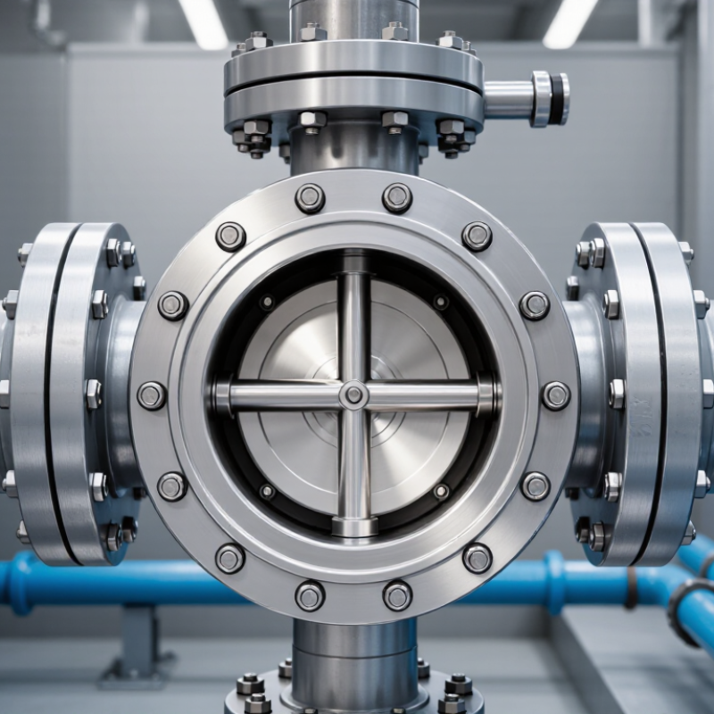
A butterfly check valve uses a circular disc to control backflow in piping systems. When fluid moves forward, pressure pushes the disc open. When flow reverses, the disc closes against its seat. This simple action protects pumps, filters, tanks, and process lines from unwanted reverse movement. Response depends on flow speed, disc weight, and installation angle.
Tip 1: Match the valve size to the pipe and operating flow. An oversized valve may close slowly and allow reverse flow. An undersized valve can create excessive pressure loss. Check pressure, temperature, fluid type, and expected flow changes. Clean water behaves differently from abrasive slurry or chemical liquid. Material selection matters.
Tip 2: Examine the closing behavior. Fast closure can reduce backflow, but it may increase water hammer. A softer closing action may protect weak pipe supports. There is no perfect setting for every system. Field experience helps, although it can sometimes lead to assumptions. Measure actual conditions instead of trusting a standard layout.
Tip 3: Install the valve where maintenance remains practical. Follow the marked flow direction and provide enough clearance for inspection. Nearby elbows, pumps, or reducers can disturb flow and affect disc movement. Keep the valve accessible. During inspections, look for seat wear, corrosion, unusual vibration, and delayed closure. Even a well-selected valve can fail when debris blocks the disc.
Match Valve Size, Pressure Class, and Flow Rate to ASME B16.34 Data
7 Tips for Choosing the Right Butterfly Check Valve
Match the valve size to the connected pipe, not only to the equipment nozzle. A larger valve may reduce velocity, but it can also weaken disc stability at low flow. Use the manufacturer’s flow coefficient data with the actual medium, temperature, and viscosity. Then compare the required flow rate with pressure loss across the valve. Keep the calculation practical. A spreadsheet can hide bad assumptions.
Tip: Check pressure class against ASME B16.34 pressure-temperature data. Confirm the valve body material, trim, and operating temperature before accepting the rating. Pressure class is not the same as working pressure at every temperature. Steam, hot water, and corrosive fluids can change the safe operating range. The data matters.
Tip: Verify the installation details. Match the face-to-face dimension, flange type, bolt pattern, and flow direction. A valve can meet its pressure class and still fail during installation. Disc clearance is easy to overlook, especially in narrow pipes. Leave room for movement.
Field reviews often find oversized check valves installed to “be safe.” That choice may create weak closing force and repeated disc movement. Undersized valves create excessive velocity and pressure loss. Neither result is ideal. Recheck the flow range, not just the maximum flow. Also review transient conditions, such as pump starts and sudden shutdowns. ASME B16.34 provides essential rating data, but proper selection still requires application-specific engineering judgment.
Compare Wafer, Lug, and Flanged Designs Using API 609 Selection Criteria
Tip 1: Start with the installation gap. Wafer butterfly check valves fit between two flanges and need less space. They are practical for compact water, air, and process piping. However, they depend on correct flange alignment and suitable bolt loading. A small misalignment can affect sealing.
Tip 2: Choose lug designs when maintenance matters. Lug valves use threaded inserts or separate bolts on each side. This arrangement allows one pipe section to be removed while the other remains supported. Check the dead-end pressure requirement carefully. Not every wafer or lug pattern is suitable for isolated service. API 609 dimensions, pressure ratings, materials, and testing requirements should guide the review.
Tip 3: Consider flanged designs for heavier service. Flanged butterfly check valves add weight and installation space, but they can offer stronger connections and easier removal. Compare the valve’s pressure-temperature rating with the actual line conditions, including surge pressure. Seat material matters near abrasive particles, hot fluids, or corrosive media. API 609 compliance alone does not guarantee perfect field performance; piping loads and reverse-flow speed still require engineering judgment. This part is often underestimated.
In real selection work, I would also inspect the disc clearance, shaft arrangement, gasket surface, and available maintenance space. A valve may meet the standard yet fail operational expectations because the closing action is too fast. Ask for documented pressure testing and material traceability. Then compare the supplier’s drawings with the actual pipe layout, not an idealized sketch.
Evaluate Materials, Temperature Limits, and Corrosion Resistance for Service
7 Tips for Choosing the Right Butterfly Check Valve
Evaluate materials, temperature limits, and corrosion resistance before approving a butterfly check valve for service. A valve may look suitable on paper. Field conditions often tell a different story. Match the body material to the pipe system, then check the disc, shaft, and seat separately. Ductile iron can suit general water duty, while stainless steel may better resist chlorides. Seat materials also matter. EPDM, NBR, and PTFE tolerate different fluids and temperatures.
Check the maximum and minimum operating temperatures, not only the catalog rating. Hot fluid, outdoor cold, and repeated thermal cycling can change sealing performance. Leave a practical margin below the stated limit. Small margins create problems. I have seen a valve pass a workshop test but leak after frequent heating and cooling. The issue was not pressure; it was hardened seat material. Review pressure, flow velocity, and installation direction together.
Corrosion resistance requires more than selecting stainless steel. Identify the fluid’s concentration, pH, chloride level, and suspended particles. Fast flow can accelerate erosion near the disc edge. Dissimilar metals may also create galvanic corrosion at connections. Request material certificates and test evidence when the service is critical. Inspect coating quality, shaft protection, and seat condition before installation. A chemical compatibility chart is useful, but it is not a field guarantee. Recheck the choice when operating conditions change.
Verify Testing, Installation Space, and Maintenance Against API 598 Requirements
Choosing the right butterfly check valve requires more than matching pipe size and pressure class. Verify the applicable API 598 edition, project specification, and service conditions before approval. Requirements can vary by application.
Request documented shell and seat leakage test results. The report should identify the valve, test medium, pressure, duration, and acceptance criteria. Confirm that gauges were calibrated and results are traceable to the valve serial number. A vague statement such as “factory tested” is not enough. If possible, witness testing or use an independent inspection record.
Installation space deserves equal attention. Measure the distance between flanges, nearby elbows, and access panels. The disc must move freely without striking a pipe, liner, or downstream component. Leave room for removing the valve and checking the shaft, seat, and fasteners. API 598 mainly addresses inspection and testing, not every physical clearance requirement. Do not confuse compliance with a complete installation design.
Maintenance planning should include isolation, draining, visual inspection, and retesting after repair. Check the flow arrow before installation. Incorrect orientation can cause serious operating problems. A common mistake is accepting a compact design without planning removal space. It looks efficient at first. Later, a small clearance can turn routine maintenance into a shutdown delay. Review the checklist again before purchase.
7 Tips for Choosing the Right Butterfly Check Valve
Verify testing, installation space, and maintenance requirements against API 598.
The chart shows the minimum shell-test duration bands specified in API Standard 598 by nominal valve size group. Always confirm the applicable API 598 edition, pressure class, valve type, and purchaser requirements before acceptance.
Testing
Request documented shell, low-pressure closure, and high-pressure closure test results where applicable. Check that the test medium, pressure, duration, and leakage acceptance criteria are recorded.
Installation Space
Allow clearance for the disc, shaft, actuator, flange bolts, insulation, inspection access, and future removal. Confirm the flow direction and required face-to-face dimensions.
Maintenance
Select replaceable seats and accessible components where possible. Establish periodic checks for external leakage, abnormal pressure loss, corrosion, and smooth non-return operation.
Reference: API Standard 598, Valve Inspection and Testing. The chart presents shell-test duration bands in seconds and is not a substitute for the governing standard or project specification.

 More
More